160-Meter Dipole Height
N0GW - Gary Wescom - 1 Nov 2006
During the current lull in solar activity, operation on the 160 meter ham band has become more popular. In the evening when most of us have time to relax and enjoy a little time on the radio, the higher frequency bands are either dead or very crowded. 160 meters, in contrast is normally open for contacts out to several hundred miles away with little interference other than static from thunderstorms. During the winter, when lightning storms are infrequent, 160 meters can be very enjoyable.
One of the reasons 160 meters remains relatively uncrowded, however, is that effective antennas for this band are very large. After all, a half wave dipole is 250 feet long. Many hams don’t have room to install one.
There are alternatives to a full size half wave dipole. The most common is the quarter wave Inverted-L. That is an end fed quarter wavelength piece of wire run vertically a high as can be managed with the remainder of the wire pulled out horizontally. Even that is 125 feet long. Plus, to perform adequately, an extensive ground radial wire installation is needed.
Fortunately, many of us in rural Missouri do have room for a 250 foot long dipole. I do. I put up a simple 160 meter Inverted-Vee configuration dipole with the center at a about 45 feet. This dipole has performed quite admirably in spited of its relatively low height.
Most text on antenna installations recommend antennas be place one half wavelength or higher for efficient operation. It is highly unlikely that I will ever have the opportunity to build any kind of antenna system that would allow me to place a dipole at that height. In fact, I doubt more than a very few hams could do so. Besides, lightning would probably disintegrate any antenna I would attempt to install that high.
So, with heights considered optimum for higher frequency bands impractical, I became curious what performance penalty a lower antenna height was causing me. I knew low dipoles worked reasonably well because most of the people I talked to on 160 meters were using them. I just didn’t know if poor performance was going unnoticed simply because everyone else was operating with the same handicap.
I set out to find the real story using EZNEC. I created a very simple flat-top dipole model for 1.9 Mhz. I calculated the expected radiation patterns, gain relative to an isotropic radiator, and losses attributable to ground proximity for heights ranging from 20 feet up to 100 feet. Table 1 shows the results of that set of calculations assuming average soil conditions.
1
|
Height (ft) |
Length (ft) |
R |
SWR |
Gain dBi |
Loss dB |
-3db elevation |
|
20 |
250 |
42 |
1.20 |
0.11 |
-7.98 |
42.5 |
|
30 |
250 |
39 |
1.30 |
2.85 |
-5.45 |
42.0 |
|
40 |
250 |
40 |
1.25 |
4.55 |
-3.83 |
41.4 |
|
50 |
250 |
43 |
1.15 |
5.59 |
-2.79 |
40.5 |
|
60 |
249 |
48 |
1.05 |
6.22 |
-2.11 |
39.4 |
|
70 |
249 |
53 |
1.05 |
6.59 |
-1.66 |
38.2 |
|
80 |
249 |
60 |
1.25 |
6.78 |
-1.35 |
36.6 |
|
90 |
249 |
66 |
1.30 |
6.85 |
-1.14 |
34.9 |
|
100 |
249 |
72 |
1.50 |
6.83 |
-0.98 |
32.9 |
Table 1 – Dipole performance over average ground.
The flat-top dipole calculations in table 1 surprised me. While, no doubt, extending the height range beyond 100 feet would have shown more variation, I was more interested in the more economically practical lower heights. 100 feet was about as high as anyone I know would ever consider for his or her antenna system. That doesn’t mean we don’t all drool over photos of really big antenna installations. We just have different priorities in our lives.
The surprise in the table was that there was only a little over a half a dB difference in gain over the 60 to 100 foot range. There was a small improvement in low angle radiation as the height was increased but neither that nor the gain difference would likely be measurable at a distant location. In fact, to produce a theoretical 3 dB decrease in gain, which might be just detectable under some conditions, dipole height would have to be dropped from 100 feet to somewhere in the 30 to 40 foot high range.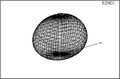
Figure 1 – Radiation pattern for dipole at 50 feet.
2
Figure 1 shows a 3 dimensional plot of the radiation pattern of a dipole mounted at 50 feet above the ground. As can be seen, its shape is roughly that of a sphere that is compressed inward slightly at the ends of the dipole elements. Maximum radiation is straight up which is good for communications out to a few hundred miles. Some other antenna type with stronger low angle radiation would probably be better for DX operation.
Restated, table 1 shows us that compared with a 160 meter dipole mounted at 100 feet above the ground, there would be essentially no detectable difference lowering it to
60 feet. Also, even down to 40 feet or so, the theoretical disadvantage is less than 3 dB. What’s more, the expected SWR on the transmission line at resonance is quite low.
OK, now that was interesting but I’ve learned that sometimes pure theoretical dipole configurations do not to match well with more realistic antenna installations. In the case of 160 meter dipoles, a flat-top configuration is not often practical. It is difficult to find two tall supports at an appropriate distance apart that would survive the tension required to hold a 250 foot long dipole straight, especially with the weight of the its feedline hanging from the middle. Most of us use an Inverted-Vee configuration on this band.
An Inverted-Vee configuration allows us to locate the high current center of the dipole high in the air while securing its ends to more convenient shorter supports. While still basically a dipole, experience and verification with past analysis showed that there are differences in how flat-top and Inverted-Vee configurations perform. I was curious if that would put the Inverted-Vee configuration at a disadvantage on 160 meters.
Table 2 shows the results of my Inverted-Vee calculations. The problem I ran into in making those calculations was with the size of the antenna. An Inverted-Vee antenna is typically defined as having an included angle of 120 degrees or less, down to minimum of about 90 degrees. The dipole halves are so long that with a 120 degree included angle, the antenna feed point would have to be higher than 60 feet just to keep their ends from touching the ground.
What I did to try to find a more reasonable set of antenna configurations to model was to simply keep the ends of the antenna at 15 feet above the ground. That was an arbitrary choice on my part but seemed to be reasonable and practical. The Vee angle then was determined simply by the geometry that resulted at each feed point height.
In general, relatively little performance was lost when compared with the flat-top dipole. The gain numbers are somewhat lower at each feed point height due to greater ground losses from parts of the antenna being closer to the ground. Another reason the gain numbers are lower is that the radiation pattern is less directional. The flat-top dipole radiation pattern was not quite circular with a small loss of low angle radiation off the ends. As may be seen in figure 2, the Inverted-Vee radiation pattern is almost perfectly circular.
3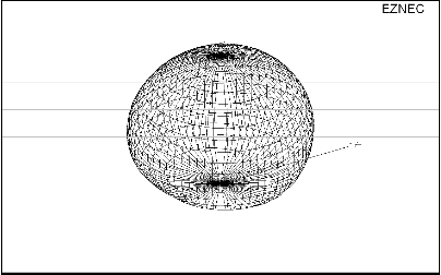
Figure 2 – Radiation pattern for Inverted-Vee at 50 feet.
As with the flat-top configuration, the Inverted-Vee configuration showed no significant performance improvement above 60 feet. Performance is still within 3 dB down to below 40 feet. Notice also the SWR column. It seems the Inverted-Vee configuration with the ends 15 feet above the ground is great for having low SWR at resonance.
|
Height (ft) |
Length (ft) |
Vee angle |
R |
SWR |
Gain dBi |
Loss dB |
-3db elevation |
|
20 |
248 |
175 |
45 |
1.10 |
-0.82 |
-8.68 |
42.6 |
|
30 |
248 |
166 |
44 |
1.15 |
0.93 |
-6.86 |
42.3 |
|
40 |
247 |
157 |
45 |
1.10 |
2.11 |
-5.59 |
41.9 |
|
50 |
246 |
147 |
46 |
1.10 |
2.92 |
-4.68 |
41.4 |
|
60 |
247 |
137 |
48 |
1.05 |
4.47 |
-4.03 |
40.8 |
|
70 |
246 |
127 |
49 |
1.00 |
3.80 |
-3.58 |
40.1 |
|
80 |
247 |
116 |
50 |
1.00 |
4.00 |
-3.26 |
39.3 |
|
90 |
248 |
106 |
50 |
1.00 |
4.09 |
-3.04 |
38.4 |
|
100 |
250 |
94 |
48 |
1.05 |
4.07 |
-2.90 |
37.3 |
Table 2 – Inverted-Vee with ends at 15 feet above the ground
So, what is the “bottom line”? A 160 meter dipole or Inverted-Vee at even modest heights can be expected to work well. Effectively, almost any horizontal antenna configuration for 160 meters is going to be a high angle radiator. It is not necessary to have your antenna mounted at 100 feet to make contacts. Stretch out your wires and join the fun.
4